
For this Assignment I chose to create a relatively simple machine, so that I could better understand the processes and behaviour of the simple linkages that I used. This proved to be a very good decision, because even given the simple nature of the mechanism it still proved to be a formidable task to decode its inner workings. The truly complex nature of simple linkages reared its ugly head while I was trying to code what I thought would be a very simple project.
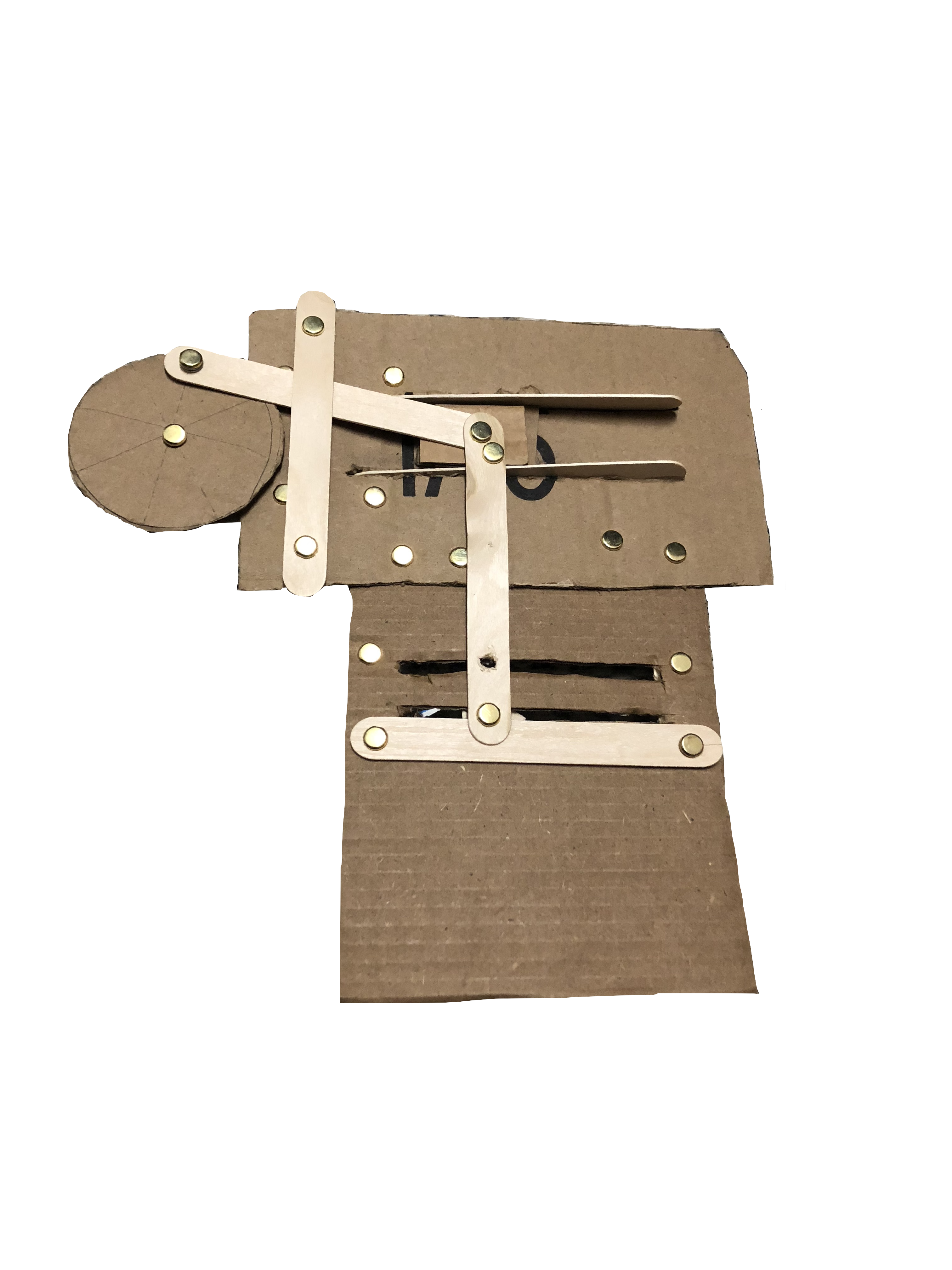
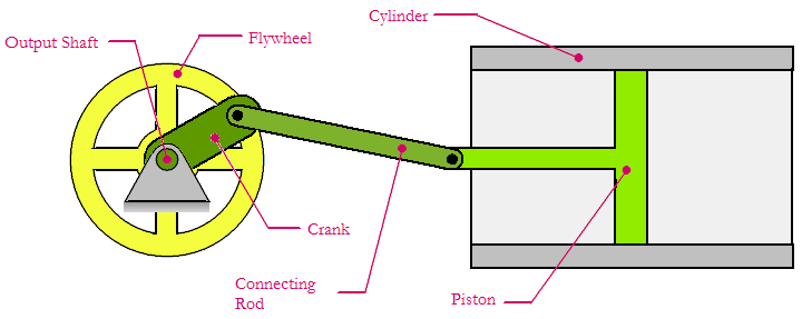
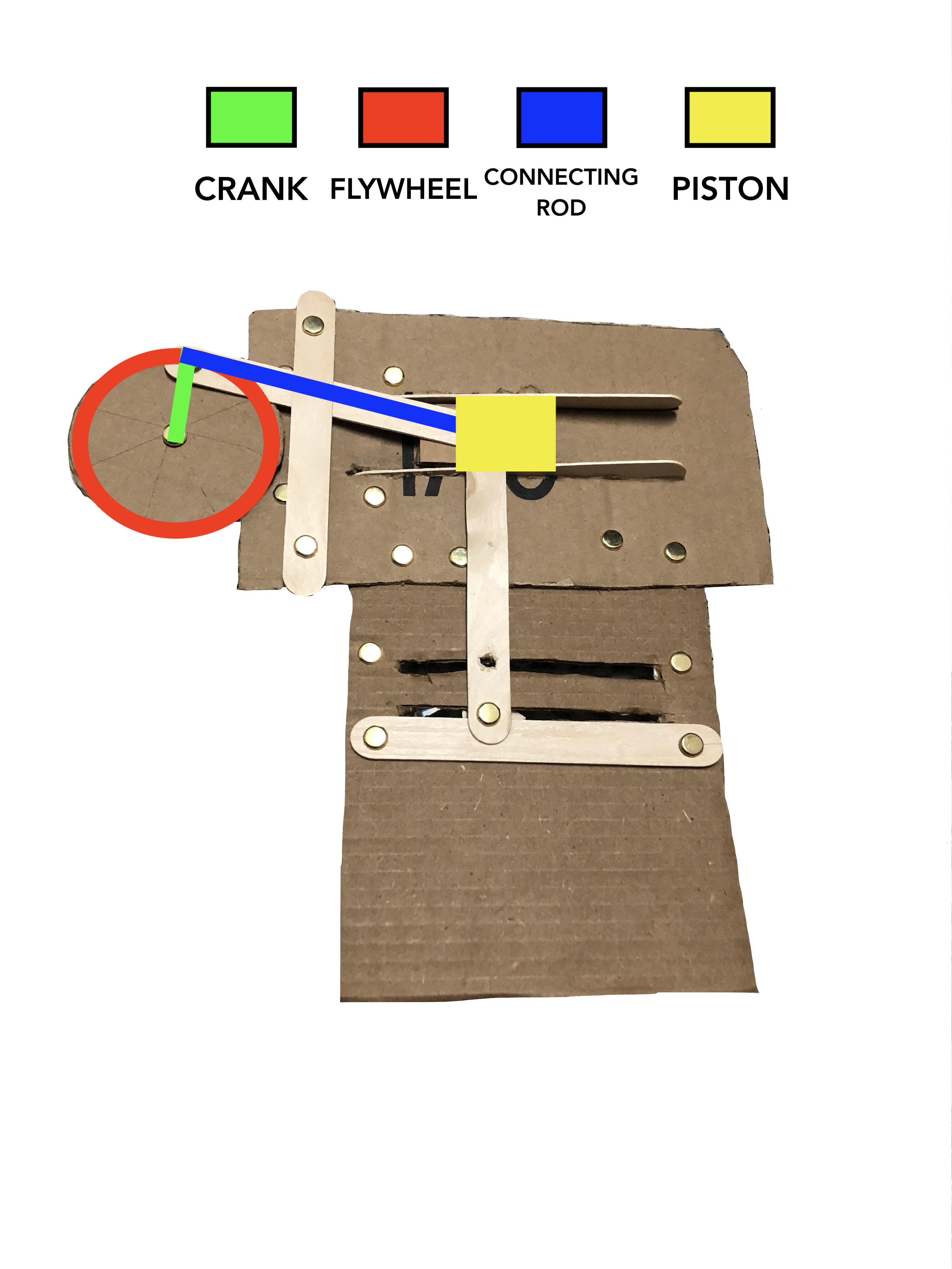
My machine, at its most simple just translates rotational motion into linear motion, basically a reverse of how a piston powers a Locomotive. Instead of the piston being powered by combustion and moving the flywheel through the connecting rod, I reversed the system and chose to have the flywheel power the piston. Instead of the output shaft being turned to generate electricity, I mounted a handle on the connection point between the crank and connecting rod, that wend through the flywheel. This enabled me to be able to turn the crank manually, and move the piston by means of the connecting rod.
For me the making of the physical machine was relatively easy. The design was pretty simple, and the only snuggle was making sure that the “piston head” would stay on the tracks that I set for them. I achieved this by adding a second track below the drawing point, so that I could ensure that the pen would move in a nearly perfect horizontal path. If I wanted to make sure that the design worked the best, I would have installed a second rotating wheel, linked to the first wheel, and the second piston.

This would have make the machine even more stable, and the drawing mechanism would have been even more accurate. Another thing that I could have done to improve the functionality of the physical machine would have been to design the piston, to have both and arm and a head, so that the linkage between the piston and connecting rod could have been smoother.
I really struggled to code the machine initially, because I was having trouble getting the point on the wheel to connect with the piston on the x-axis. I figured out that I could just offset the x axis point on the end of the connecting rod by the same amount as the x position of the point at the end of the crank. After doing this it worked perfectly.
While designing this mechanism I was fascinated by the concept of what I was doing and why I was designing it the way I was. In Machine Art in the 20th Century Broeckmann states that “Many other objects … are the result of conscious artistic intention. For in a great many useful objects function does not dictate form, it merely indicates form in a general way. The role of the artist in machine art is to choose, from a variety of possible forms each of which may be functionally adequate, that one form which is aesthetically most satisfactory. He does not embellish or elaborate, but refines, simplifies and perfects.” This described very accurately my process of designing this machine. I could have found ways to optimize its functionality, but instead some part of my brain chose to make the machine the way that I did, for no other reason than I simply liked the way it looked. This project for me was the perfect intersection between art and mathematical design.


